Software
Robot
Requirements
In order to communicate with the robot through the micro USB the FTDI driver need to be installed. If a serial port is automatically created when connecting the robot to the computer you’re done otherwise you need to download the drivers for your system and architecture:
- Windows Vista/XP, Windows 7/8 (run as administrator)
- Ubuntu: when the robot is connected the port will be created in
/dev/ttyUSB0(no need to install a driver) - Mac OS X 10.3 to 10.8 (32 bit), Mac OS X 10.3 to 10.8 (64 bit), Mac OS X 10.9 and above; after installing the driver the port will be created in
/dev/tty.usbserial-...; you can find a guide on how to install the driver in the following link AN_134_FTDI_Drivers_Installation_Guide_for_MAC_OSX.pdf
All the drivers can be found in the official page from the following link FTDI drivers.
AVR Studio 4 project
The projects are built with AVR Studio 4 released by Atmel.
Basic demo
This project is thought to be a starting point for Elisa-3 newbie users and basically contains a small and clean main with some basic demos selected through the hardware selector that show how to interact with robot sensors and actuators. The project source can be downloaded from Elisa-3 basic firmware source; the hex file can be directly downloaded from Elisa-3 basic firmware hex. To program the robot refer to section Programming.
Selector position and related demo:
- 0: no speed controller activated => free running (all others positions have the speed controller activated)
- 1: obstacle avoidance enabled
- 2: cliff avoidance enabled (currently it will simply stop before falling and stay there waiting for commands)
- 3: both obstacle and cliff avoidance enabled
- 4: random RGB colours and small green LEDs on
- 5: robot moving forward with obstacle avoidance enabled and random RGB colours
Advanced demo
This is an extension of the basic demo project, basically it contains some additional advanced demos. The project source can be downloaded from Elisa-3 advanced firmware source; the hex file can be directly downloaded from Elisa-3 advanced firmware hex. To program the robot refer to section Programming.
Selector position and related demo:
- 0: no speed controller activated => free running (all others positions have the speed controller activated)
- 1: obstacle avoidance enabled
- 2: cliff avoidance enabled (currently it will simply stop before falling and stay there waiting for commands)
- 3: both obstacle and cliff avoidance enabled
- 4: random RGB colours and small green LEDs on
- 5: robot moving forward with obstacle avoidance enabled and random RGB colours
- 6: robot testing and address writing through serial connection
- 7: automatic charging demo (refer to section Videos), that is composed of 4 states:
- random walk with obstacle avoidance
- search black line
- follow black line that lead to the charging station
- charge for a while
- 8: autonomous odometry calibration
- 9: write default odometry calibration values in EEPROM (hard-coded values); wait 2 seconds before start writing the calibration values
- 10: robot moving forward (with pause) and obstacle avoidance enabled; random RGB colours and green led effect
- 11: local communication: robot alignment
- 12: local communication: 2 or more robots exchange data sequentially
- 13: local communication: listen and transmit continuously; when data received change RGB colour
- 14: local communication: RGB color propagation
- 15: clock calibration (communicate with the PC through the USB cable to change the OSCCAL register); this position could also be used to remote control the robot through the radio (only speed control is enabled)
Arduino IDE project
The project is built with the Arduino IDE 1.0 freely available from the official Arduino website. In order to build the Elisa-3 firmware with the Arduino IDE 1.0 the following steps has to be performed:
- download the Arduino IDE 1.0 (later versions should be also fine, refer to Arduino Software) and extract it, let say in a folder named “arduino-1.0“
- download the Elisa-3 library and extract it within the libraries folder of the Arduino IDE, in this case “arduino-1.0\libraries“; you should end up with a “Elisa3” folder within the libraries. If you start the Arduino IDE now you can see that the Elisa-3 library is available in the menu “Sketch=>Import Library…“
- the file boards.txt in the Arduino IDE folder “arduino-1.0\hardware\arduino” need to be changed to contain the definitions for the Elisa-3 robot, add the following definitions at the end of the file:
##############################################################

elisa3.name=Elisa 3 robot

elisa3.upload.protocol=stk500v2
elisa3.upload.maximum_size=258048
elisa3.upload.speed=57600

elisa3.bootloader.low_fuses=0xE2
elisa3.bootloader.high_fuses=0xD0
elisa3.bootloader.extended_fuses=0xFF
elisa3.bootloader.path=stk500v2-elisa3
elisa3.bootloader.file=stk500v2-elisa3.hex
elisa3.bootloader.unlock_bits=0x3F
elisa3.bootloader.lock_bits=0x0F

elisa3.build.mcu=atmega2560
elisa3.build.f_cpu=8000000L
elisa3.build.core=arduino
elisa3.build.variant=mega

##############################################################
- download the Elisa-3 project file and open it with the Arduino IDE (you should open the file “elisa3.ino“)
- select “Elisa-3 robot” from the “Tools=>Board” menu; click on the “Verify” button to build the project
- to upload the resulting hex file, attach the micro usb and set the port from the “Tools=>Serial Port” menu consequently; turn on the robot and click on the “Upload” button
You can download the Arduino IDE 1.0.5 for Linux (32 bits) containing an updated avr tool-chain (4.5.3) and the Elisa3 library from the following link arduino-1.0.5-linux32.zip.
If the Tools->Serial Port menu is grayed out then you need to start the Arduino IDE in a terminal typing sudo path/to/arduino.
If you want to have access to the compiler options you can download the following project Elisa3-arduino-makefile.zip that contains an Arduino IDE project with a Makefile, follow the instructions in the “readme.txt” file in order to build and upload to the robot.
Aseba
Refer to the page Elisa-3 Aseba.
Matlab
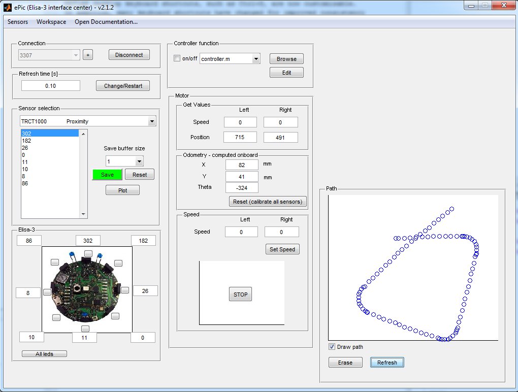
The ePic2 Matlab interface was adapted to work with the Elisa-3 robot. The communication is handled with the radio module. Both Matlab 32 bits and 64 bits are supported (tested on Matlab R2010a) Follow these steps to start playing with the interface:
- program the robot with the advanced demo
- place the selector in position 15 (to pilot the robot through the interface with no obstacle and no cliff avoidance)
- connect the radio base-station to the computer
- download the ePic2 for Elisa-3 and extract it
- open (double click) the file main.m; once Matlab is ready type main+ENTER and the GUI should start
- click on the + sign (top left) and insert the robot address (e.g 3307), then click on Connect
Webots simulator
The following features have been included in the Elisa-3 model for the Webots simulator:
- proximity sensors
- ground sensors
- accelerometer
- motors
- green leds around the robot
- RGB led
- radio communication
You can download the Webots project containing the Elisa-3 model (proto) and a demonstration world in the following link Elisa-3-webots.zip.
You can download a Webots project containing a demonstration world illustrating the usage of the radio communication between 10 Elisa-3 robots and a supervisor in the following link Elisa-3-webots-radio.zip. Here is a video of this demo:
On-board behaviours
The released firmware contains two basic on-board behaviours: obstacle and cliff avoidance. Both can be enabled and disabled from the computer through the radio (seventh bit of flags byte for obstacle avoidance, eight bit of flags byte for cliff avoidance).
The following videos show three robots that have their obstacle avoidance enabled:
Programming
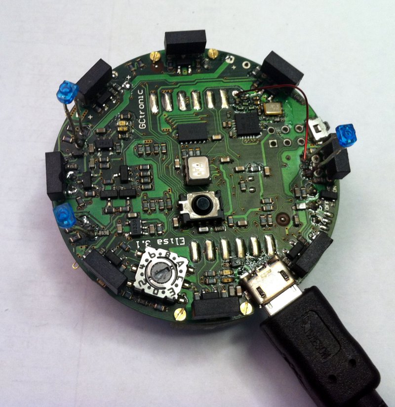
The robot is pre-programmed with a serial boot-loader. In order to upload a new program to the robot a micro USB cable is required. The connection with the robot is shown below:
If you are working with the Arduino IDE you don’t need to follow this procedure, refer instead to section Arduino IDE project.
If you encounter some problem during programming (e.g. time-out problems) you can try following this sequence: turn on the robot, unplug the robot from the computer, plug the robot into the computer, it will make some blinks; when the blinks terminate execute the programming command again.
Beware that every time you need to re-program the robot you need to unplug and plug again the cable to the computer.
Windows 7
- Download the Burn-O-Mat-Windows7.zip Windows 7 package and extract it. The package contains also the FTDI driver.
- Execute the script
config.batand follow the installation; beware that this need to be done only once. The script will ask you to modify the registry, this is fine (used to save application preferences). - Connect the robot to the computer; the COM port will be created.
- Run the application
AVR Burn-O-Mat.exe; you need to configure the port to communicate with the robot:- click on
Settings => AVRDUDE - in the
AVRDUDE Options, onPortenter the name of the port just created when the robot was connected to the computer (e.g. COM10); then clickOk
- click on
- In the
Flashsection search the hex file you want to upload on the robot. - Turn on the robot, wait the blinks terminate and then click on
Writein theFlashsection. - During the programming the robot will blink; at the end you’ll receive a message saying
Flash successfully written.
Mac OS X
The following procedure is tested in Max OS X 10.10, but should work from Mac OS X 10.9 onwards; in these versions there is built-in support for the FTDI devices.
- Download the Mac OS X package and extract it.
- Execute the script
config.shin the terminal, it will ask you to install the Java Runtime Environment; in case there is a problem executing the script try withchmod +x config.shand try again. Beware that this need to be done only once. - Connect the robot to the computer; the serial device will be created (something like
/dev/tty.usbserial-AJ03296J). - Run the application
AVR Burn-O-Mat; you need to configure the port to communicate with the robot:- click on
Settings => AVRDUDE - in the
AVRDUDE Options, onPortenter the name of the port just created when the robot was connected to the computer; then clickOk
- click on
- In the
Flashsection search the hex file you want to upload on the robot. - Turn on the robot, wait the blinks terminate and then click on
Writein theFlashsection. - During the programming the robot will blink; at the end you’ll receive a message saying
Flash successfully written.
Linux
The following procedure was tested in Ubunut 12.04, but a similar procedure can be followed in newer systems and other Linux versions.
You can find a nice GUI for avrdude in the following link http://burn-o-mat.net/avr8_burn_o_mat_avrdude_gui_en.php; you can download directly the application for Ubuntu from the following link avr8-burn-o-mat-2.1.2-all.deb.
Double click the package and install it; the executable will be avr8-burn-o-mat.
Beware that the application requires the Java SE Runtime Environment (JRE) that you can download from the official page http://www.oracle.com/technetwork/java/javase/downloads/index.html, alternatively you can issue the command sudo apt-get install openjdk-8-jre in the terminal.
The application need a bit of configuration, follow these steps:1. connect the robot to the computer, the serial device will be created (something like /dev/USB0)2. to use the USB port the permissions need to be set to read and write issueing the command sudo chmod a+rw /dev/ttyUSB03. start the application and click on Settings => AVRDUDE4. set the location of avrdude and the related configuration file (refer to the previous section when avrdude was installed to know the exact location); the configuration file is in/etc/avrdude.conf3. click OK, close the application and open it again (this is needed to load the configuration file information); click on Settings => AVRDUDE4. select stk500v2 as the Programmer5. set the serial port connected to the robot (/dev/ttyUSB0)6. in additional options insert -b 57600, you will end up with a window like the following one:
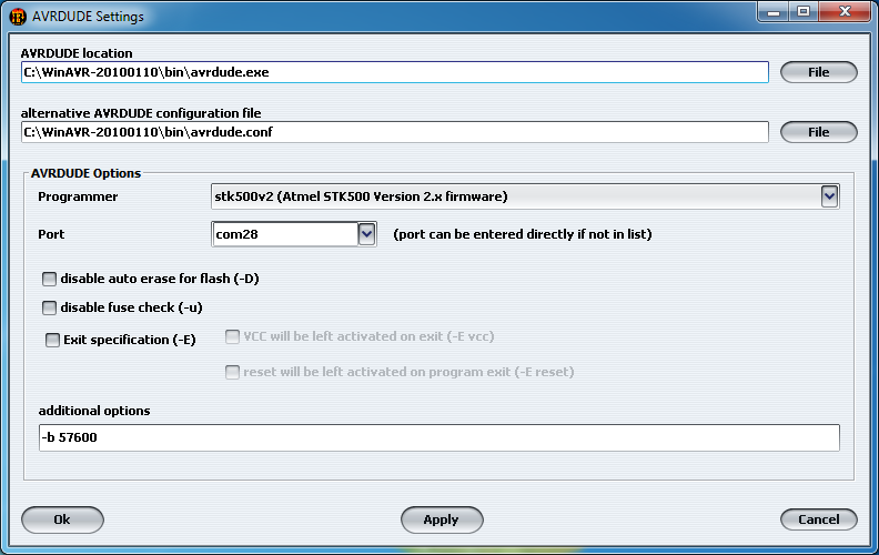
7. click OK; select ATmega2560 in the AVR type8. in the Flash section search the hex file you want to upload on the robot; select Intel Hex on the right9. connect the robot to the computer, turn on the robot, wait the blinks terminate and then click on Write in the Flash section10. during the programming the robot will blink; at the end you’ll receive a message saying Flash successfully written.
Command line
The avrdude utility is used to do the upload, you can download it directly from the following links depending on your system:
- Windows;
avrdudewill be installed in the pathC:\WinAVR-20100110\bin\avrdude; avrdude version 5.10 - Mac OS X;
avrdudewill be installed in the path/usr/local/CrossPack-AVR/bin/avrdude; to check the path issue the commmandwhich avrdudein the terminal; avrdude version 6.0.1 - Ubuntu (12.04 32-bit): issue the command
sudo apt-get install avrdudein the terminal;avrdudewill be installed in the path/usr/bin/avrdude; to check the path issue the commandwhich avrdudein the terminal; avrdude version 5.11.1
Open a terminal and issue the command avrdude -p m2560 -P COM10 -b 57600 -c stk500v2 -D -Uflash:w:Elisa3-avr-studio.hex:i -v
where COM10 must be replaced with your com port and Elisa3-avr-studio.hex must be replaced with your application name; in Mac OS X the port will be something like/dev/tty.usbserial-..., in Ubuntu will be /dev/ttyUSB0.
The Basic demo and Advanced demo have this command contained in the file program.bat in the default directory within the project, this can be useful for Windows users.
Internal EEPROM
The internal 4 KB EEPROM that resides in the micro-controller is pre-programmed with the robot ID in the last two bytes (e.g. if ID=3200 (0x0C80), then address 4094=0x80 and address 4095=0x0C). The ID represents also the RF address that the robot uses to communicate with the computer and is automatically read at start-up (have a look a the firmware for more details).
Moreover the address 4093 is used to save the clock calibration value that is found during production/testing of the robots; this value hasn’t to be modified otherwise some functionalities such as tv remote control could not work any more. For more information on clock calibration refers to the application note AVR053: Calibration of the internal RC oscillator.
The Elisa-3 robot supports an autonomous calibration process and the result of this calibration is saved in EEPROM starting at address 3946 to 4092.
The size of usable EEPROM is thus 3946 bytes (0-3945) and the remaining memory must not be modified/erased.
In order to program the eeprom an AVR programmer is required, we utilize the Pocket AVR Programmer from Sparkfun (recognized as USBtiny device); then with the avrdudeutility the following command has to be issued:
avrdude -p m2560 -c usbtiny -v -U eeprom:w:Elisa3-eeprom.hex:i -v -B 1
where Elisa3-eeprom.hex is the EEPROM memory saved as Intel Hex format (eeprom example); a possible tool to read and write Intel Hex format is Galep32 from Conitec Datensysteme.
Alternatively a program designed to writing to these EEPROM locations can be uploaded to the robot, in case an AVR programmer isn’t available. The project source can be downloaded from Elisa3-eeprom-write.zip; it is simply needed to modify the address, rebuild and upload to the robot.
Boot-loader
In case the boot-loader of the Elisa-3 is erased by mistake, then you can restore it by using an AVR programmer. You can download the boot-loader from here stk500v2.hex; the source code is available here bootloader-stk500v2.zip.Avrdude can be used to actually write the bootloader to the robot with a command similar to the following one:avrdude -p m2560 -c stk500v2 -P COM348 -v -U lfuse:w:0xE2:m -U hfuse:w:0xD8:m -U efuse:w:0xFF:m -V -U flash:w:stk500v2.hex:i -v -B 2
Here we used a programmer recognized as a serial device (port COM348) that utilizes the stk500v2 protocol.
Base-station
This chapter explains informations that aren’t needed for most of the users since the radio module is ready to be used and don’t need to be reprogrammed. Only if you are interested in the firmware running in the radio module and on how to reprogram it then refer to section http://www.gctronic.com/doc/index.php/Elisa#Base-station (chapter 4.2) of the Elisa robot wiki.
PC side
This section gives informations related to the radio module connected to the computer; if you don’t have a radio module you can skip this section.
Elisa-3 library
This library simplify the implementation of applications on the pc side (where the RF module is connected) that will take control of the robots and receive data from them. Some basic examples will be provided in the following sections to show how to use this library.
The project is built with Code::Blocks (mingw) and requires libusb-1.0 since it is used to communicate with the radio base-station, you can directly download it from the following link http://libusb-winusb-wip.googlecode.com/files/libusb_2011.07.06.7z. The source code of the library can be downloaded from pc-side-elisa3-library.
Compilation on Windows:
- within the libusb-1.0 package you’ll find the header “libusb.h” (under /include/libusb-1.0/) and the library “libusb-1.0.a” (in this case under /MinGW32/static/ since we use MinGW) that should be copied or referenced in the compiler headers/libraries
- add the linker flag “-lusb-1.0” in the project in order to build successfully (the Code::Blocks project has already set it)
Compilation on Linux / Mac OS X:
- required libraries: libusb-1.0, libusb-1.0-dev, libncurses5, libncurses5-dev
- build: under the “/linux” folder within the project directory there is a makefile, simply type make on a terminal to build the library
Windows 10
Windows 10 users need to work with an updated version of the libusb library; the version 1.0.20 is knwown to work and can be directly downloaded from http://sourceforge.net/projects/libusb/files/libusb-1.0/libusb-1.0.20/libusb-1.0.20.7z/download, following versions should also work.
To build the Elisa-3 library and related demos with this updated version of libusb, the mingw-w64 compiler need to be used.
Multi-platform Monitor
The demo is a command line monitor that shows all the sensors information (e.g. proximity, ground, accelerometer, battery, …) and let the user move the robot and change its colours and behaviour with the keyboard. The data are sent using the protocol described in the previous section.
The following figures show the monitor on the left and the available commands on the right.
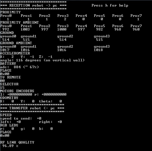
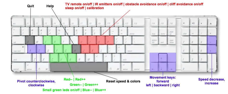
The project is built with Code::Blocks (mingw) and requires the Elisa-3 library.
The source can be downloaded from pc-side single robot.
Windows
Execution:
- install the driver contained in the nRFgo Studio tool if not already done; this let the base-station be recognized as a WinUSB device (boot-loader), independently of whether the libusb library is installed or not
- once the driver is installed, the pre-compiled “exe” (under \bin\Debug dir) should run without problems; the program will prompt you the address of the robot you want to control
Compilation:
the Code::Blocks project should already be setup to reference the Elisa-3 library headers and lib files, anyway you need to put this project within the same directory of the Elisa-3 library, e.g. you should have a tree similar to the following one:
- Elisa-3 demo (parent dir)
- pc-side-elisa3-library (Elisa-3 library project)
- pc-side-elisa3-library-1-robot (current project)
Linux / Mac OS X
The project was tested to work also in Ubuntu and Mac OS X (no driver required).
Compilation:
- you need to put this project within the same directory of the Elisa-3 library
- build command: go under “linux” dir and type “make”
Execution:
- sudo ./main
Communicate with 4 robots simultaneously
This example shows how to interact with 4 robots simultaneously, basically it shows the sensors information (proximity and ground) coming from 4 robots and let control one robot at a time through the keyboard (you can change the robot you want to control). The project requires the Elisa-3 library; the source can be downloaded from pc-side 4 robots. For building refer to the section Multiplatform monitor.
Obstacle avoidance
This demo implements the obstacle avoidance behaviour controlling the robot from the pc through the radio; this means that the robot reacts only to the commands received using the basic communication protocol and has no intelligence on-board. The demo uses the information gathered from the 3 front proximity sensors and set the motors speed accordingly; moreover the RGB LEDs are updated with a random colour at fixed intervals.
The project requires the Elisa-3 library; the source can be downloaded from pc-side-obstacle-avoidance. For building refer to the section Multiplatform monitor.
The following video shows the result:
It is available also the same example but with 4 robots controlled simultaneously; the source can be downloaded from pc-side-obstacle-avoidance-4-robots
It is easy to extend the previous example in order to control many robots, here is the code that controls 8 robots simultaneously pc-side-obstacle-avoidance-8-robots.
Cliff avoidance
This demo implements the cliff avoidance behaviour controlling the robot from the pc through the radio; as with the obstacle avoidance demo, the robot reacts only to the commands received from the radio. The demo uses the information gathered from the 4 ground sensors to stop the robot when a cliff is detected (threshold tuned to run in a white surface); moreover the RGB LEDs are updated with a random colour at fixed intervals.
The project requires the Elisa-3 library; the source can be downloaded from pc-side-cliff-avoidance. For building refer to the section Multiplatform monitor.
The following video shows the result:
Set robots state from file
This project show how to send data to robots for which we will know the address only at runtime, in particular the content of the packets to be transmitted is parsed from a csv file and the interpreted commands are sent to the robots one time. The project requires the Elisa-3 library; the source can be downloaded from pc-side from file. For building refer to the section Multiplatform monitor.