Elisa-3

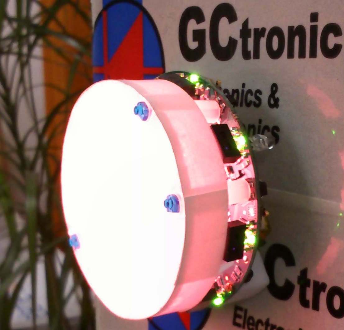
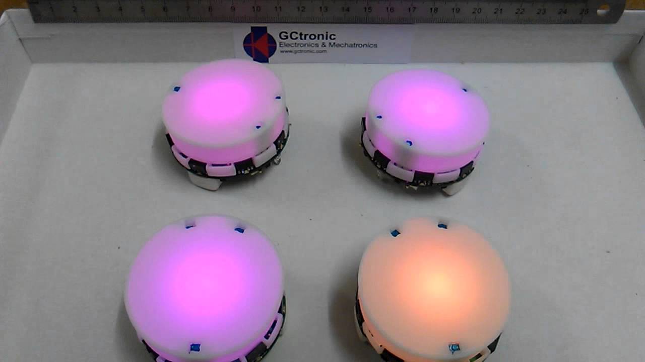
Elisa-3 is a low cost Miniature swarm robot include fast radio, 8 proximity, 4 ground sensors, 3D accelerometer and top RGB LED.

OVERVIEW

HARDWARE

COMMUNICATION

SOFTWARE

ODOMETRY

TRACKING

LOCAL COMMUNICATION

ROS

VIDEOS

Overview

Elisa-3 is an evolution of the Elisa robot based on a different micro-controller and including a comprehensive set of sensors:

  • Atmel 2560 micro-controller (Arduino compatible)
  • Central RGB led
  • 8 green leds around the robotIRs emitters8 IR proximity sensors (Vishay Semiconductors Reflective Optical Sensor)
  • 4 ground sensors (Fairchild Semiconductor Minature Reflective Object Sensor)
  • 3-axis accelerometer (Freescale MMA7455L)
  • RF radio for communication (Nordic Semiconductor nRF24L01+)
  • Micro USB connector for programming, debugging and charging
  • IR receiver
  • 2 DC motors
  • Top light diffuser
  • Selector

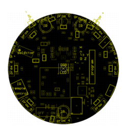
The robot is able to self charge using the charger station, as shown in the previous figure. This figure illustrates the position of the various sensors.

Useful information

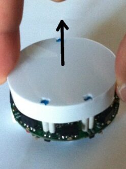
The top light diffuser and robot are designed to lock together, but the diffuser isn't fixed and can thus be removed as desired; the top light diffuser, as the name suggests, helps the light coming from the RGB led to be smoothly spread out, moreover the strip attached around the diffuser let the robot be better detected from others robots. Once the top light diffuser is removed, pay attention not to look at the RGB led directly. In order to remove the top light diffuser simply pull up it, then to place it back on top of the robot remember to align the 3 holes in the diffuser with the 3 IRs emitters and push down carefully until the diffuser is stable; pay attention to not apply too much force on the IRs emitters otherwise they can bend and stop working.

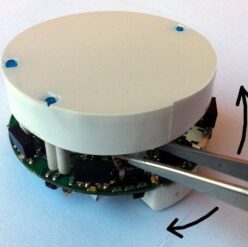
When the top light diffuser is fit on top of the robot, then in order to change the selector position you can use the tweezers; the selector is located near the front-left IR emitter, as shown in the figure.

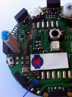
If you encounter problems with the radio communication (e.g. lot of packet loss) then you can try moving the antenna that is a wire near the robot label. Place the antenna as high as possible, near the plastic top light diffuser; try placing it in the borders in order to avoid seeing a black line on the top light diffuser when the RGB led is turned on.

Robot Charging

Elisa-3 can be piloted in the charger station in order to be automatically self charged; there is no need to unplug the battery for charging. The following figures shows the robot approaching the charger station; a led indicates that the robot is in charge:

Micro-controller is informed when the robot is in charge and this information is also transferred to the PC in the flags byte; this let the user be able to pilot the robot to the charger station and be informed when it is actually in charge. More information about the radio protocol can be found in the section Communication.

Moreover the robot is also charged when the micro USB cable is connected to a computer; pay attention that if the USB cable is connected to a hub, this one need to be power supplied.

Following video shows the Elisa-3 piloted through the radio to the charging station using the monitor application:

Top light diffuser

From February 2013 onwards the Elisa-3 is equipped with a new top light diffuser designed to fit perfectly in the 3 IRs emitters of the robot. The diffuser is made of plastic (3d printed), it is more robust and it simplifies the removal and insertion. Here is an image:


HARDWARE

Following figures show the main components offered by the Elisa-3 robot and where they are physically placed:

Power Autonomy

The robot is equipped with two batteries for a duration of about 3 hours at normal usage (motors run continuously, IRs and RGB leds turned on).

Detailed Specifications


COMMUNICATION

Wireless

Radio base-station is connected to the PC through USB and transfers data to and from the robot wirelessly. In the same way the radio chip (nRF24L01+) mounted on the robot communicates through SPI with the micro-controller and transfers data to and from the PC wirelessly. The robot is identified by an address that is stored in the last two bytes of the micro-controller internal EEPROM; the robot firmware setup the radio module reading the address from the EEPROM. This address corresponds to the robot id written on the label placed under the robot and should not be changed.

Packet format - PC to radio to robot

13 bytes payload packet format is shown below (the number in the parenthesis expresses the bytes) :

Optimised Protocol

Communication between the pc and the base-station is controlled by the master (computer) that continuously polls the slave (base-station); the polling is done once every millisecond and this is a restriction on the maximum communication throughput. To overcome this limitation we implemented an optimized protocol in which the packet sent to the base-station contains commands for four robots simultaneously; the base-station then separate the data and send them to the correct robot address. The same is applied in reception, that is the base-station is responsible of receiving the ack payloads of 4 robots (64 bytes in total) and send them to the computer. This procedure let us have a throughput 4 times faster.

Packet format - robot to radio to PC

The robot send back to the base-station information about all its sensors every time it receive a command; this is accomplished by using the "ack payload" feature of the radio module. Each "ack payload" is 16 bytes length and is marked with an ID that is used to know which information the robot is currently transferring. The sequence is the following (the number in the parenthesis expresses the bytes):

Pay attention that the base-station could return "error" codes in the first byte if the communication has problems:

  • 0 => transmission succeed (no ack received though)
  • 1 => ack received (should not be returned because if the ack is received, then the payload is read)
  • 2 => transfer failed

Packet ID 3:

  • Prox* contain values from 0 to 1023, the greater the values the nearer the objects to the sensor
  • The Flags byte contains these information:

. bit0: 0 = robot not in charge; 1 = robot in charge

. bit1: 0 = button pressed;1 = button not pressed

. bit2: 0 = robot not charged completely; 1 = robot charged completely

. the remainig bits are not used at the moment

Packet ID 4:

  • Prox4 contains values from 0 to 1023, the greater the values the nearer the objects to the sensor
  • Ground* contain values from 512 to 1023, the smaller the value the darker the surface
  • AccX and AccY contain raw values of the accelerometer; the range is between -64 to 64
  • TV remote contains the last interpreted command received through IR

Packet ID 5:

  • ProxAmbient* contain values from 0 to 1023, the smaller the values the brighter the ambient light
  • Selector contains the value of the current selector position

Packet ID 6:

  • ProxAmbient4 contains values from 0 to 1023, the smaller the values the brighter the ambient light
  • GroundAmbient* contain values from 0 to 1023, the smaller the values the brighter the ambient light
  • AccZ contains raw values of the accelerometer; the range is between 0 and -128 (upside down)
  • Battery contains the sampled value of the battery, the values range is between 780 (battery discharge and 930 (battery charged)

Packet ID 7:

  • LeftSteps and RightSteps contain the sum of the sampled speed for left and right motors respectively (only available when the speed controller isn't used; refer to xpos, ypos and theta when the speed controller is used)
  • theta contains the orientation of the robot expressed in 1/10 of degree (3600 degrees for a full turn); available only when the speed controller is enabled
  • xpos and ypos contain the position of the robot expressed in millimeters; available only when the speed controller is enabled


ODOMETRY

Odometry of Elisa-3 is quite good even if the speed is only measured by back-emf. On vertical surfaces the absolute angle is given by the accelerometer measuring g... quite a fix reference without drifting 😉

A fine calibration of the right and left wheel speed parameters might give better results. However the current odometry is a good estimate of the absolute position from a starting point. The experiments are performed on a square labyrinth and the robot advances doing obstacle avoidance. The on-board calculated (x,y,theta) position is sent to a PC via radio and logged for further display.

Details about the code can be found in the advanced-demo project, in particular the motors.c source file. The PC application used for logging data is the monitor

Autonomous Calibration

Since the motors can be slightly different a calibration can improve the behavior of the robot in terms of maneuverability and odometry accuracy. An autonomous calibration process is implemented onboard: basically a calibration is performed for both the right and left wheels in two modes that are forward and backward with speed control enabled. In order to let the robot calibrate istelf a white sheet in which a black line is drawed is needed; the robot will measure the time between detection of the line at various speeds. The calibration sheet can be downloaded from the following link calibration-sheet.pdf.

In order to accomplish the calibration the robot need to be programmed with the advanced firmware and a specific command has to be sent to the robot through the radio module or the TV remote; if you are using the radio module you can use the monitor application in which the letter l (el) is reserved to launch the calibration, otherwise if you have a TV remote control you can press the button 5. The sequence is the following:

1. put the selector in position 8

2. place the robot near the black line as shown below; the left motor is the first to be calibrated. Pay attention to place the right wheel as precise as possible with the black line

3. once the robot is placed you can type the l (el) command (or press the button 5); wait a couple of minutes during which the robot will do various turns at various speed in the forward direction and then in the backward direction

4. when the robot terminated (robot is stopped after going backward at high speed) you need to place it in the opposite direction in order to calibrate the right motor, as shown below.

5. once the robot is placed you can type again the l (el) command (or press the button 5)

6. when the robot finish, the calibration process is also terminated.

The previous figures show a robot without the top diffuser, anyway you don't need to remove it!


TRACKING

Assembly documentation

You can download the documentation from here tracking-doc.pdf.

Have a look also at the video:

SwisTrack

Some experiments are done with the SwisTrack software in order to be able to track the Elisa-3 robots through the back IR emitter, here is a resulting image with 2 robots:

Pre-compiled SwisTrack software (Windows) can be downloaded from the following link SwisTrack-compiled. The video shows the tracking of 5 robots.

The SwisTrack software lets you easily log also the resulting data that you can then elaborate, here is an example taken from the experiment using 5 robots:

Position Control

We developed a simple position control example that interacts with Swistrack through a TCP connection and control 4 robots simultaneously; the orientation of the robots is estimated only with the Swistrack information (delta position), future improvements will integrate odometry information. The following video shows the control of 4 robots that are driven in a 8-shape.

All the following projects require the Elisa-3 library, for building refer to the section Multiplatform monitor.

One of the characteristics of the Elisa-3 robot is that it can move in vertical thanks to its magnetic wheels, thus we developed also a vertical position control that use accelerometer data coming from the robot to get the orientation of the robot (more precise) instead of estimating it with the Swistrack information, you can download the source code from the following link:

We developed also an example of position control that control a single robot (code adapted from previous example) that can be useful during the initial environment installation/testing; you can download the source code from the following link:

Another good example to start playing with the tracking is an application that lets you specify interactively the target point that the robot should reach; you can download the source code of this application from the following link:

Utilities

In order to adjust the IR camera position it is useful to have an application that turn on the back IR of the robots. The following application back-IR-on-4-robots-rev182-30.06.14.zip is an example that turn on the back IR of 4 robots, their addresses are asked to the user at the execution.


LOCAL COMMUNICATION

Advanced firmware is needed in order to use the local communication. You can find some examples on how to use this module in the main, refers to demos in selector position from 11 to 14.Here are some details about the current implementation of the communication module:

  • use the infrared sensors to exchange data, thus during reception/transmission the proximity sensors cannot be used to avoid obstacles; in the worst case (continuous receive and transmit) the sensor update frequency is about 3 Hz
  • bidirectional communication
  • id and angle of the proximity sensor that received the data are available
  • the throughput is about 1 bytes/sec
  • maximum communication
  • distance is about 5 cm
  • no reception/transmission queue (only one byte at a time)
  • the data are sent using all the sensors, cannot select a single sensor from which to send the data. The data isn't sent contemporaneously from all the sensors, but the sensors used are divided in two groups of 4 alternating sensors (to reduce consumption)


VIDEOS

Autonomous charge

The following videos show 3 Elisa-3 robots moving around in the environment avoiding obstacles thanks to their proximity sensors and then going to the charging station autonomously; some black tape is placed in the charging positions to help the robots place themselves thanks to their ground sensors. The movement and charging is independent of the gravity. It works also vertically and up-side-down.

Remote control

This video shows 38 Elisa-3 robots moving around with onboard obstacle avoidance enabled; 15 of them are running autonomously, the remaining 23 are controlled from one computer with the radio module.